
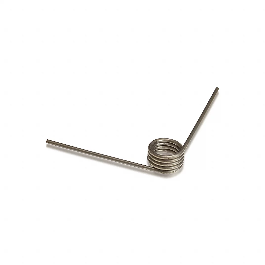
If you’ve read our previous pieces on compression versus extension testing and on reading force-deflection curves, you already know the basic logic of spring testing: apply a controlled load, measure the response, compare it against spec. Torsion springs follow that same logic, but almost nothing else about the process carries over cleanly.
Compression and extension springs move in a straight line. You push or pull, and a load cell reads force against displacement. Torsion springs don’t move in a straight line at all — they rotate around an axis, storing energy as torque rather than linear force. That difference changes the fixture, the sensor, the units on the chart, and the failure modes you’re watching for. A tester built around a load cell and a crosshead simply can’t produce a meaningful torsion curve, no matter how well it’s calibrated for compression work.
This matters more than it might sound like on paper. Torsion springs show up in some of the highest-consequence applications a spring manufacturer touches — garage door counterbalance systems, seatbelt retractors, hinge and latch mechanisms, clothespin-style clips, circuit breakers. When a torsion spring is out of spec, it usually fails quietly at first — a hinge that feels slightly off, a latch that doesn’t quite hold — before it fails completely. Testing is what catches that gap before the part ships.
What Torsion Testing Actually Measures
A torsion spring is defined by two numbers a customer cares about: torque and angular deflection. Torque is the rotational force the spring produces or resists, typically expressed in inch-pounds or newton-meters. Angular deflection is how far the spring’s legs rotate from their free position, expressed in degrees or turns. Plot one against the other and you get the torsional equivalent of a force-deflection curve — a torque-angle curve — and it tells you the same kind of story: is the spring’s rate linear through its working range, does it match the design rate, and does it return cleanly to its starting position without taking a permanent set.
The math behind that rate is straightforward in principle. Spring rate in torsion is driven by wire diameter, mean coil diameter, number of active coils, and the wire’s shear modulus — increase wire diameter and rate goes up sharply, since it scales with the fourth power of diameter; add active coils and rate drops. None of that is unique to testing. What testing confirms is whether the physical part actually behaves the way that math predicted, because coiling tension, wire consistency, and heat treatment all introduce variation that a calculation alone won’t catch.
How a Torsion Tester Is Built Differently
Where a compression tester clamps a spring between two flat platens, a torsion tester holds the spring by its body — usually on a mandrel or arbor sized to the spring’s inside diameter — and engages the legs with an actuator that rotates rather than pushes. The core measurement device is a torque transducer instead of a load cell, and the motion system needs to control angle precisely, since angular deflection is the independent variable you’re setting, not just something you happen to measure.
Fixturing is where a lot of the real engineering happens. Every torsion spring has a different leg configuration — straight legs, hook ends, tangent legs bent to a custom angle — and the fixture has to grip that geometry without introducing its own friction or slippage into the reading. A loose or misaligned mandrel shows up in the data as noise or as an artificially soft-looking curve, and it’s one of the more common sources of bad readings on torsion equipment that isn’t dialed in for the part.
Good torsion testing also takes a specific approach to minimize friction and hysteresis error: approaching the target angle from both directions — under-rotating and over-rotating slightly, then averaging — cancels out a lot of the mechanical friction that would otherwise skew a single-pass reading. It’s a small procedural detail, but it’s the difference between a torque-angle curve you can trust and one that just looks plausible.
Testing in Both Directions Matters
Torsion springs are directional in a way compression and extension springs generally aren’t. A spring wound to resist rotation in one direction can behave differently when tested the other way, and many real applications — hinges that open and close, mechanisms that cycle back and forth — load the spring in both directions over its service life. Testing only the “wind” direction and assuming the “unwind” direction matches is a common shortcut that misses real failure modes, particularly set and hysteresis differences between directions.
This is also where cyclic testing intersects with torsion work. A single torque-angle pull tells you the spring meets rate spec today. Cycling it through repeated rotations — the same underlying idea we covered in our fatigue testing article — is what tells you whether that rate holds up over the thousands or millions of cycles the application actually demands. For a garage door spring rated for tens of thousands of open-close cycles, a single static torque reading is necessary but nowhere near sufficient.
Common Failure Signatures in Torsion Data
A few patterns show up often enough in torsion testing to be worth knowing before you’re staring at a screen trying to interpret one:
A curve that starts steep and then flattens usually points to coil binding or interference somewhere in the spring body — coils touching each other before the design intended them to, which changes the effective number of active coils mid-travel.
A spring that doesn’t return to its original angular position after load is removed has taken a permanent set, almost always from being deflected past its elastic limit during forming, heat treatment, or handling. This is the torsion equivalent of a compression spring that’s lost free length.
Inconsistent torque readings at the same angle across repeated cycles, rather than a smooth settling pattern, often trace back to fixture slippage or a mandrel that doesn’t match the spring’s actual inside diameter closely enough.
A rate that measures correctly but is noticeably different between the first cycle and steady-state cycles later on is a sign the spring needs a pre-set or scragging step in manufacturing — deliberately deflecting it beyond working range once, before testing, to stabilize the material.
Why This Belongs in Your Testing Program, Not Just Your Design Process
It’s tempting to treat torsion spring behavior as something that gets settled at the design and coiling stage and only needs a final go/no-go check. In practice, torsion springs are more sensitive to manufacturing variation than compression springs of similar size, because leg position, coiling tension, and heat treatment all directly affect torque output in ways that are harder to catch visually than a compression spring’s free length. A torsion tester built for the geometry you’re actually producing — not a general-purpose load frame pressed into service — is what turns that variation into a measurable, correctable number instead of a field complaint.
If you’re running torsion spring production and testing it on equipment that wasn’t built for rotational loading, or you’re evaluating whether your current setup is actually catching the failure modes above, that’s exactly the kind of conversation worth having before the next production run rather than after a customer return.